Table of Contents
This is the documentation for the EmlaLockSafe. The sources can be found under https://github.com/hugo3132/EmlaLockSafe.

Changelog of Documentation
- 2022-01-03:
- Added a note to Using the Safe which describes that the safe can be remote controlled.
- 2022-04-09:
- Updated link to stl file in I/O module
- Fixed broken chapter Main Configuration Server
- Updated how links are displayed in Controller board
- Added alternative source for the safe to Hardware Description
- Added descriptions and links to the brackets created by naatisab to Controller board and I/O module
- 2022-04-15:
- Added pictures of the brackets created by naatisab to Controller board and I/O module
- 2022-05-24:
- Added description of new Housing
- Moved everything housing related to Mounting Electronics to Safe
Setup the Safe
Howto Flash the Software
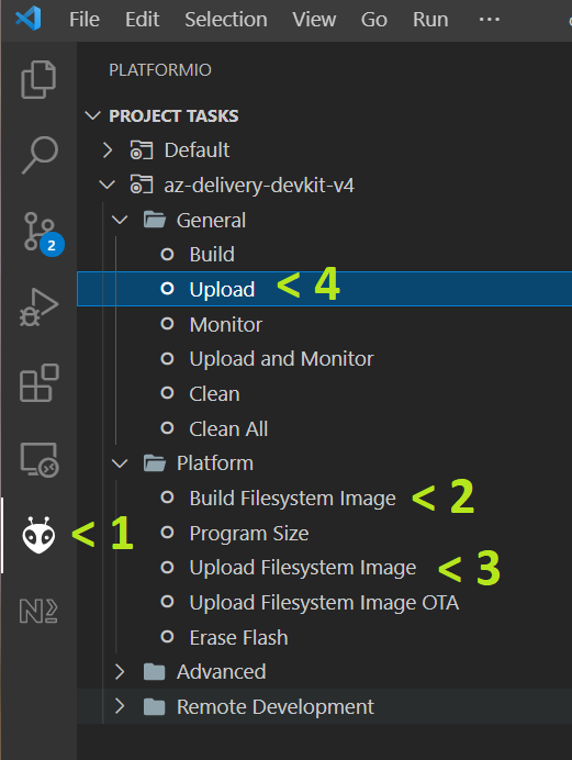
For the development on arduino the free Visual Studio Code together with the extension PlatformIO was used. After both are installed and the controller board is connected to the computer, the folder software must be opened in Visual Studio Code. selected to create an image containing everything from the data folder. Next, Upload Filesystem Image must be selected to flash the data folder to the controller board. Finally, Upload should be selected to compile and upload the firmware:
WiFi Configuration
After the firmware is flashed and the filesystem is uploaded the controller should automatically reboot and show the following on the display:
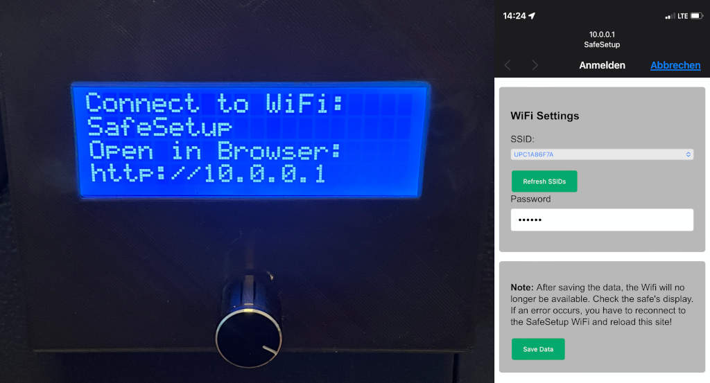
Since your WiFi credentials are not known yet, the controller creates a new WiFi called "SafeSetup". After connecting to the "SafeSetup" WiFi the WiFi configuration website should open automatically. If not, try to manually navigate to the website http://10.0.0.1. On the website you should select your WiFi and enter the password which is required to connect to the network. After selecting Save Data the controller will reboot and connect to your WiFi. If anything goes wrong, you can always reset everything by flashing the filesystem image (see Howto Flash the Software).
For the detailed description of the software behind this chapter please refer to WiFi Configuration Server.
Software Configuration
After the controller rebooted and has connected to the WiFi a webserver is started. The address of the webserver is shown in the display:
Since the controller is now part of your normal network it can be reached by any computer, phone, ... connected to your network.
For the detailed description of the software behind this chapter please refer to Main Configuration Server.
Using the Safe
The main interaction with the safe is done using the display and the encoder knob. It is alsso possible to remote control the inferface over the same webpage as used in Software Configuration (e.g. http://emlalocksafe). Everything which is displayed on the LCD is handled by so called views. One variant of such views are menus:
A menu always consists of a menu title and several menu items. A menu item can be selected by rotating the encoder. To execute the action associated with the selected item the encoder must be pushed. In case not all menu items fit onto the display, a scrollbar is displayed and the menu items are distributed to different pages.When the software of the safe is booted it enters the Normal Operation Mode. In case there are problems with the software, the safe can be started into Safe Mode.
- Note
- To be able to use the Safe Mode, it is recommended to use a photo of the Emlalock Unlock Key Menu as combination picture when setting up a new emlalock session!
Safety Aspects
The safe depends on an external 5V power supply. Therefore, it is recommended to have an charged powerbank to be able to use the safe even if there is an power outage.
The software is designed to make use of emlalock but not fully rely on its availability. The locking itself is not driven by the emlalock site. There is the field LockState::endDate. If it is after the current timestamp the safe will open. All values of the class LockState are stored in the internal flash memory. Therefore, it won't be lost in case of power failures.
As long as there is an internet connection and the emlalock site is available, the LockState::endDate is updated with the values of your current session. If there are connection problems the LockState::endDate is just no longer updated.
In all cases a correct system time is required to evaluate the LockState::endDate. To be independent of an working internet connection, a real-time clock module (RTC) is used. The RTC has its own battery which will keep the clock running if no external power source is connected. When the software is booting it first sets the internal system to the time provided by the RTC. As soon as a internet connection is available, the system time is synchronized with the internet using the network time protocol (NTP). The more accurate internet time is than used to update the RTC module. Therefore, the system time can be always assumed to be correct.
In addition, a Safe Mode is implemented which allows to open safe with a code.
- Warning
- In case the end date is not visible in your session, it cannot be read over the API as well. Therefore, the safe can only be open if the connection to the emlalock site works. Alternatively, the Safe Mode must be used.
- Note
- At least in my case the mechanical keyhole is covered by the housing of the display. Therefore, I can store the mechanical key next to the safe and just smash the display housing with an hammer in case of an emergency.
Normal Operation Mode
Assume the safe is already properly configured as described in the previous chapter. After a reboot the software will activate the Locked View in case you are in a session or if a manual timer was set. As soon as the EmlaLock API detects that a session was created, the safe will enter the Locked View as well. In case a hygiene opening is started on the emlalock site, the Hygiene Opening Menu will be activated.
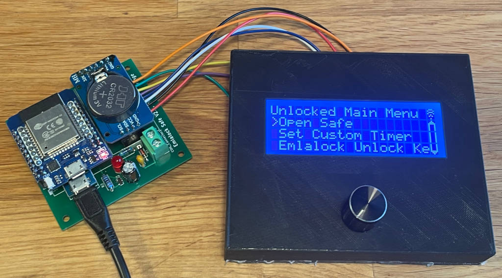
In case no session is active, the Unlocked Main Menu will be displayed.
Locked View
This view is always displayed if the safe is locked by an active session. Dependent on the configuration of the emlalock session or the manual timer, the displayed content differs. The first line always shows the message that the safe is locked as well as the current system time.
The first example shows the passed time, and time which is left as well as the end date. The second example shows the content of the display in case only the temperature should be shown as indication of the time left.
Unlocked Main Menu
In case the safe should not be locked this is the main menu.
From the main menu the following can be done:
- Open safe: After selecting this option, the software will trigger a refresh of the emlalock safe. In case there is still no session active, the coil will be pulled an the safe can be opened. In case a session was created in the meantime, the safe will enter the Locked View.
- Set Custom Timer: With this option the Manual Timer Mode can be configured.
- Emlalock Unlock Key: This option will activate the Emlalock Unlock Key Menu. In the Emlalock Unlock Key Menu the emergency unlock key is displayed and can be changed (see also Safe Mode).
- Preferences: Opens the Preferences Menu.
- Hardware Test View: Starts the Hardware Test View which allows to see the state of the RTC and test the encoder and coil. The view can only be left by disconnecting the power supply.
- Reboot: Reboots the controller.
Emlalock Unlock Key Menu
This menu can be entered using the Unlocked Main Menu. It shows the current emergency unlock key which can be used to unlock the safe in the ref subSafeMode. A photograph of this view should be used as combination picture for your emlalock session.
It is also possible to select generate a new key. The previous key will then no longer be valid.
Preferences Menu
This menu can be entered using the Unlocked Main Menu.
The following actions can be selected:
- Change Wifi Settings: Deletes the WiFi credentials and restarts the controller. After the reboot the controller will start the WiFi Configuration server.
- Start Configuration Server: Activates the Software Configuration server.
- Restore Factory Defaults: Deletes all configuration data. After the reboot the controller will start the WiFi Configuration server.
- Back: Return to the Unlocked Main Menu.
Hardware Test View
This view can be used to test the hardware. As soon as it is activated, the coil is pulled and released with 0.5Hz. In addition, if the encoder nob used the action is diplayed. Finally the current time of the real-time clock (R) and local system time (S) is displayed.
- Note
- The RTC is always set to UTC.
Hygiene Opening Menu
This menu is activated in case a hygiene opening is started on the emlalock site.
From the menu the following can be done:
- Open safe: After selecting this option, the software will trigger a refresh of the emlalock safe. In case the hygiene opening is still active, the coil will be pulled an the safe can be opened.
- Emlalock Unlock Key: This option will activate the Emlalock Unlock Key Menu. In the Emlalock Unlock Key Menu the emergency unlock key is displayed and can be changed (see also Safe Mode).
In addition, the time left in the hygiene opening is displayed.
Manual Timer Mode
The manual timer mode is an alternative to emlalock. It allows to lock the safe for a certain time. From the Unlocked Main Menu the entry Set Custom Timer should be selected to start the Set Timer View.
Set Timer View
The view allows to set the a custom timer. The number marked with "> <" can be changed by rotating the encoder. To switch to the next number the encoder must be pressed. At the bottom, the computed end date is displayed. After the time is set and confirmed, Select Display Time Passed will be displayed next.
Select Display Time Passed
After the time is set, the this view allows to select if the the time passed should be displayed or not. If Yes or No is selected, the view Select Display Time Left will be activated. If Cancel is selected, the safe will return to the Unlocked Main Menu.
Select Display Time Left
This this view allows to select if the the time left should be displayed or not. After selecting Yes, No or Temperature, the safe will be locked until the time is up. If Cancel is selected, the safe will return to the Unlocked Main Menu.
Safe Mode
The safe mode can be used to open the safe in case of software problems. As long as the safe is unlocked the Emlalock Unlock Key Menu can be opened to display or change the emergency unlock key. To enter the safe mode, the encoder nob must be pressed while connecting the power supply. If the nob is pressed during booting, the Emergency Enter Menu View is displayed. After 2 seconds the safe will enter the Emergency Menu without connecting to the WiFi.
Emergency Enter Menu View
Emergency Menu
The emergency menu allows to select one of the following actions:
- Unlock with key: Opens the Emergency Enter Key View to open the safe with the emergency unlock key
- Start Wifi: Connects to the WiFi and continues booting
- Offline Mode: Continues booting without connecting to the WiFi
Emergency Enter Key View
In this view the emergency key can be entered to unlock the safe. The letter marked with "> <" can be changed by rotating the encoder nob. To switch to the next letter, the nob must be pushed.
After entering the last character of the key, the key is verified. If the correct key was entered, the safe unlocks.
Hardware Description
Understanding the locking mechanism
I've used a cheap safe from a local hardware store. This safe from amazon was successfully tested as well. But any cheap safe should do the trick as long as it can be electronically unlocked and easily disassembled. Try to look for a safe which is powered by 4 batteries (4 x 1.5V). Then the chances are high that the 5V of the controller board are high enough to pull the coil. The cheaper the safe the easier it might be to drill the holes into it to mount everything. After removing the cover on the inside of the safe, the original electronics board can be removed and the mechanism looks as follows:
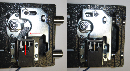
On the left side of the picture the safe is locked. The pin of the coil is pushed upwards by a spring and the mechanism is blocked. As soon as a current is applied to the coil, the pin is pulled down and the safe can be opened. The mechanism is also the reason why these safe must be mounted to something solid (e.g. a wall). Otherwise you can hit the safe from the top which pushes down the spring for a few milliseconds in which the safe can be unlocked.
New electronics
The idea of this project is now to replace the original electronics with a controller which checks the EmlaLock API if it can be opened or not. To be able to connect to the internet I first started using a ESP8266. After a while I ran out of memory while parsing the JSON file delivered by the EmlaLock API. Therefore, I had to switch to the more powerful ESP32 D1 mini module. The controller module is extended by a real-time clock (RTC) module. As long as the controller has a WiFi connection the time of the RTC module is set using the network time protocol. In case the WiFi connection is lost the controller is able to get the time from the RTC module even after the power outage (see also Safety Aspects). This is important in case the Manual Timer Mode is used.
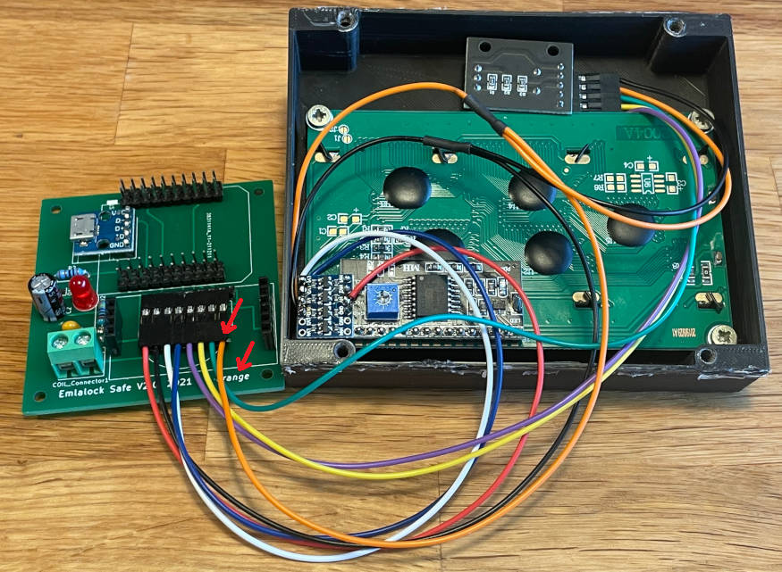
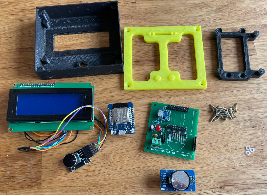
The controller and RTC module are both part of the Controller board which is mounted inside the safe. The Controller board is extended by the I/O module mounted to the outside of the safe which contains a HD44780 display with an I²C converter and a rotary encoder. Since the controller display requires 5V and the controller runs with 3.3V, a logic level converter is added between the controller board and the LCD module.
Controller board
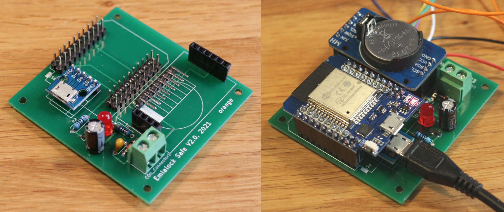
The controller board contains the ESP32 controller and the RTC as well as some electronics which can open the coil. The controller board is mounted inside the safe to ensure the firmware cannot be modified while the safe is locked. For the power supply of the controller a USB cable without data-pins should be used (either by disconnecting them or using a USB power cable).

A two-layer board layout can be found under hardware. I also added the files I've used when I ordered the PCB from jlcpcb under hardware/JLCPCB Job. The assembled board looks like:
I/O module
The I/O module is responsible for displaying the current state and is therefore mounted to the outside of the safe. It consists of:
- HD44780 based LCD module
- HD44780 to I2C converter
- logic level converter
- rotary encoder

Mounting Electronics to Safe
Version 1 by Hugo3132
In the first version only one 3D printed part was necessry containg everything from the I/O module. The STL file can be downloaded from hardware/3d printed parts/LCD Housing by hugo3132. The case itself was created using the free version of onshape. If it should be modified you can use the following link and modify it to your own needs. The LCD housing is mounted by drilling some holes into the metal of the safe and screwing it from the inside. The Controller board is mounted by using some screws to the inner plastic cover of the safe.
Extension of Version 1 by naatisab
Naatisab created some 3D printed brackets which can be used to mount the LCD housing without drilling into the safe (see hardware/3d printed parts/Emla Safe mounting brackets by naaitsab).
For the I/O module no PCB is required. Everything is directly soldered to each other or connected with some cables.
Originally, the controller board was mounted by drilling some holes directly into the original plastic cover of the mechanics (see picture at the very top of this page). Naatisab created an alternative 3d-printed PCB holder which replaces the original plastic cover by a 3D printed holder. It can be found under hardware/3d printed parts/Emla Safe mounting brackets by naaitsab:
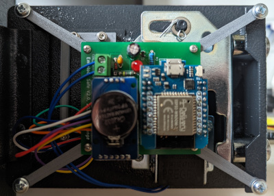
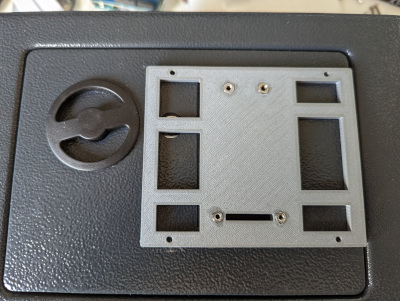
Version 2 by Hugo3132
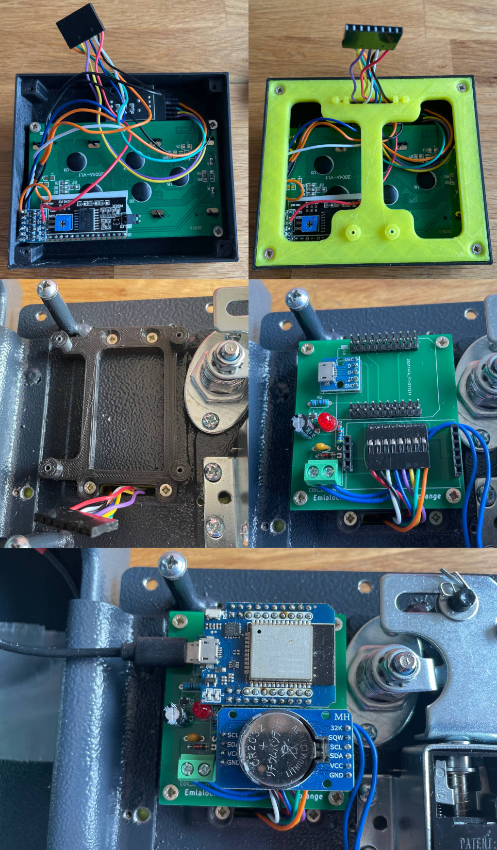
Inspired by the extension I've created a completly new design for the 3D printed parts using FreeCAD. For the new design 3 parts must be printed, 15 2x12mm screws and 3 washers are required:
The washers are required to first mount the LCD module to the Front Panel. Then, the mounting frame 1 is mounted to the panel. From inside the safe, the mounting frame 2 is mounted to the first frame through the door of the safe. Finally, the PCB is mounted to the second frame and everything is connected:
Overview about Software
The EmlaLockSafe uses an ESP32 processor board to open the attached safe dependent on your session on emlalock.com. The software running on the EPS32 is separated into different parts which are described in the following sections.
The first section covers how the webservers are used to configure the software. The section Lockstate shows how the software handles if it should open or not and what is shown on the display. The section EmlaLock API shows how the software interacts with the API of emlalock.com.
Except of the WiFi Configuration Server, everything what is displayed on the LCD is using Views. A view can be what's currently displayed, a dialog or an menu. For the navigation within the views, the encoder nob can be used.
- Warning
- If the filesystem in the flash memory (SPIFFS) is accessed the interrupts must be temporarily deactivated. The class UsedInterrupts provides an attach and detach function to temporarily deactivated the interrupts. An other option is to use the function executeWithoutInterrupts which accepts a lamda expression which is executed while the interrupts are detached.
Configuration
The configuration is stored in the fields of the configuration::Configuration class. It automatically loads and saves all parameters to the file /configuration.txt. The filesystem is located in an SPIFFS in the ESP32's flash memory. To change the configuration two webservers are used. The first sever (see WiFi Configuration Server) is always started automatically when the WiFi credentials are not complete. The second server (see Main Configuration Server) is automatically started if the EmlaLock API is not configured. Both servers can also be started using the Preferences Menu. The webservers are derived configuration::ConfigurationServerBase. The base class provides the function addSpiffsFileToServer() which makes a file in the SPIFFS available on the webserver. In addition, jquery and the main CSS file is added.
WiFi Configuration Server
The server is started as soon as the WiFi SSID or password is empty in the configuration::Configuration class. Since the WiFi credentials are not known, the ESP32 acts as access point with the SSID SafeSetup (see createAp()). Additionally, a DNS server is started which resolves any request to the IP address of the ESP32. This is necessary to implemented a captive portal which automatically forwards any client which connects to the WiFi to the configuration website. If the captive portal does not work, the necessary steps are also displayed on the LCD:

The webserver mainly provides the indexWifi.html (see configureWebserver()). It also provides a generated text-file with all visible WiFi networks. The list is automatically updated in the loop() function.
Main Configuration Server
The main configuration server is a webserver to configure everything except of the WiFi settings. The main website provided by the server is the file indexConfig.html (preview without backend indexConfig.html). The webserver is automatically started and stopped by the views::ConfigurationServerView. As mentioned before, the view and therefore also the webserver is activated automatically after a reboot if the EmlaLock API is not configured. When the views::ConfigurationServerView is active, it provides a menu entry to reset the WiFi settings and reboot. After the reboot, the WiFi Configuration Server will be automatically started. This might become necessary if the software is not able to connect to your WiFi. In addition, the WiFi Configuration Server shows the IP which can be used to access the configuration site.
Currently the following values can be set:
Emlalock Settings
- User ID
- API Key
- The Emergency Key
- The behavior in case a session is ended as failed session
Miscellaneous Settings
- Timezone
- Backlight Timeout
Hygiene Opening Settings
- AutoLock after time is over
Time Restrictions Settings
It is possible to limit the time when the safe can be opened. The specified time span can be applied one or several of the following aspects:
- the normal unlock function
- the configuration server
- unlock during hygiene openings
- unlock using the emergency key
Lockstate
TBD
EmlaLock API
TBD
Views
The views itself are described in Using the Safe. All views are global and can be accessed over the ViewStore.
TBD